Testing
Testing for this project will allow for verification of the reliability and functionality of the payload. Testing will also allow for the confirmation of reaching the success criteria and requirements. Testing will have to be done in a smaller scale and in a controlled environment, to get accurate results as a full launch and landing will have too many variables. Most tests will involve stress testing the assembled payload to ensure that it can withstand the forces its expected to experience.
Stress testing of the various parts mostly consisted of applying forces to various parts till it broke or bent. This method allows for a simulation of how these parts would perform during flight and landing. for example the connector plate needed to survive the central rod pushing into it, because if it broke then the rod would crush the electronics on the other side. The plates ability to withstand a shear force to its center was tested by using the Instron to apply a force to the center of the plate till it broke in order to see how much it could withstand. One issue that came up in testing was during the spring test. The method for testing the forces needed to extend the spring, was to hang weights to the end of the rod assembly and allow those to pull down. this method did not work for testing the compression of the spring due to the weights awkwardly hanging against the spring and rod assembly. This method was later changed so that the force was applied manually while the assembly sat on a scale to measure the force.
First Test Flight

Head plate Strength test
The purpose of this test was to determine the strength of the head plate and how much force it would take before breaking. in addition this test included a new design to compare against the old design. To pass this test, the part would need to survive at least 300lbs of force to the center and it was predicted that the new design would be 10-20% more effective.
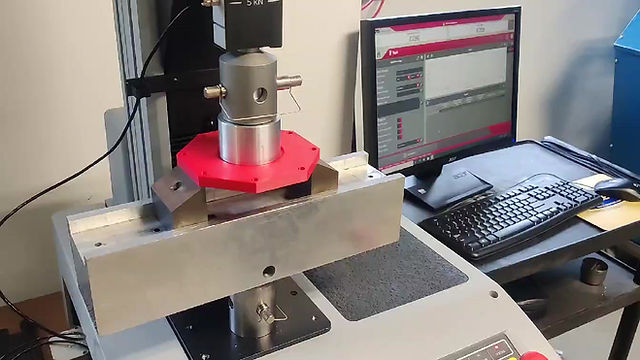
This test was preformed using an Instron machine in a simply supported beam configuration. force was slowly applied to the center till the part buckled and the data was graphed by the machine in a force vs. displacement chart.

Specimen 1 (new)

Specimen 2 (new)


Specimen 3 (old)


Specimen 4 (old)


Table of Results
The Results of this test show that the parts all broke after 350lbs, passing the requirement, but the new design was only 1-5% better than the old one. this is actually good enough for the rocket because the new design is also lighter by 10g, so it saves some weight will still being slightly stronger. one thing to note about the test is that realistically the had plate is supported on all sides by a 0.5in thick wall that runs along the perimeter instead of only on the two sides, meaning that in reality the parts should be stronger than the test shows.
Spring Test
As referenced before, the spring test was to measure the forces required to fully extend and compress the spring. The inclusion of the extension test was only after the rod assembly had overextend and dislocated during an ejection test. This test involves applying force to the small rod of the assembly and measuring how far it displaces from neutral until it reaches its limits.
Test Materials

Spring Extension Test

Spring Compression Test

Spring Test Data

The data shows the force needed to over extend the spring is 69.1605N or ~15.54lbf and that it has a displacement of 14.5in, which is measured from the end of the large rod to the end of the small rod. The displacement at neutral was 9.25in and the max compression was at 1in with a force of 122.48N or ~27.53lbf. The data shows that the spring can support the weight of the payload five times over. in addition this data can be used with hooks law to calculated the spring constant of this spring. The spring tested was found to have a spring constant of 3.16 lbf/in which is alsightly higher than the manufacturers 2.95 lbf/in.
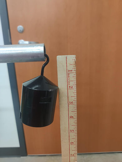
Rod Deflection Test
The purpose of this test is to measure the rods modulus of elasticity by simulating a cantilever beam. The data can then be used to calculate the the Pcr for column buckling. The importance of thus test is that it allows for the strength of the rod to be tested and calculated without the need to perform destructive buckling tests.
Test Set up

1Kg weight
5Kg weight

Data
Calculations


Results
The calculations show that the average Modulus of elasticity is 25.06 Gpa with the highest being 36.3 Gpa. These numbers are far below the usual 70 Gpa for aluminum. this was likely due to the low amount of weight used in this test, as the measured modulus increased as more weight was added and likely would have reached 70 Gpa by 10Kg.
Using this data, the Pcr for this column can be calculated. using 25.06 Gpa, the average, the Pcr is 4.89 KN or about 1100 lbf. This means that the test passes the requirement of the rod surviving 300 lbf.